(b) if a 23-v emf is connected to the terminals a and b, what is the current in resistor r1?
Learning Objectives
By the end of this section, you lot will exist able to:
- Compare and contrast the voltage and the electromagnetic force of an electrical power source.
- Draw what happens to the terminal voltage, electric current, and power delivered to a load as internal resistance of the voltage source increases (due to aging of batteries, for example).
- Explain why information technology is beneficial to use more than ane voltage source connected in parallel.
When you forget to turn off your car lights, they slowly dim equally the battery runs down. Why don't they simply glimmer off when the battery'due south energy is gone? Their gradual dimming implies that battery output voltage decreases as the battery is depleted. Furthermore, if you lot connect an excessive number of 12-V lights in parallel to a car battery, they volition be dim even when the battery is fresh and even if the wires to the lights accept very low resistance. This implies that the bombardment's output voltage is reduced by the overload. The reason for the decrease in output voltage for depleted or overloaded batteries is that all voltage sources have two fundamental parts—a source of electric energy and an internal resistance. Let us examine both.
Electromotive Force
Y'all can think of many unlike types of voltage sources. Batteries themselves come in many varieties. At that place are many types of mechanical/electrical generators, driven by many different energy sources, ranging from nuclear to current of air. Solar cells create voltages directly from light, while thermoelectric devices create voltage from temperature differences. A few voltage sources are shown in Figure one. All such devices create a potential deviation and can supply electric current if connected to a resistance. On the minor scale, the potential difference creates an electric field that exerts force on charges, causing current. We thus utilise the proper name electromotive strength, abbreviated emf. Emf is non a force at all; it is a special blazon of potential difference. To be precise, the electromotive force (emf) is the potential difference of a source when no electric current is flowing. Units of emf are volts.

Effigy ane. A variety of voltage sources (clockwise from top left): the Brazos Wind Farm in Fluvanna, Texas (credit: Leaflet, Wikimedia Commons); the Krasnoyarsk Dam in Russia (credit: Alex Polezhaev); a solar farm (credit: U.Due south. Section of Energy); and a grouping of nickel metallic hydride batteries (credit: Tiaa Monto). The voltage output of each depends on its structure and load, and equals emf only if there is no load.
Electromotive strength is directly related to the source of potential departure, such as the particular combination of chemicals in a battery. Yet, emf differs from the voltage output of the device when electric current flows. The voltage across the terminals of a battery, for case, is less than the emf when the battery supplies current, and information technology declines further as the battery is depleted or loaded down. Nevertheless, if the device's output voltage can exist measured without drawing current, then output voltage will equal emf (fifty-fifty for a very depleted bombardment).
Internal Resistance
Equally noted before, a 12-V truck battery is physically larger, contains more charge and energy, and can deliver a larger current than a 12-V motorbike battery. Both are pb-acrid batteries with identical emf, but, because of its size, the truck battery has a smaller internal resistance r . Internal resistance is the inherent resistance to the menses of current inside the source itself. Effigy 2 is a schematic representation of the two fundamental parts of whatsoever voltage source. The emf (represented by a script E in the figure) and internal resistance r are in series. The smaller the internal resistance for a given emf, the more current and the more than ability the source can supply.
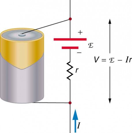
Figure 2. Whatsoever voltage source (in this case, a carbon-zinc dry out cell) has an emf related to its source of potential difference, and an internal resistance r related to its construction. (Note that the script E stands for emf.). Also shown are the output terminals across which the terminal voltage V is measured. Since V = emf − Ir, final voltage equals emf merely if there is no electric current flowing.
The internal resistance r can carry in circuitous ways. As noted, r increases as a battery is depleted. But internal resistance may also depend on the magnitude and direction of the current through a voltage source, its temperature, and even its history. The internal resistance of rechargeable nickel-cadmium cells, for case, depends on how many times and how deeply they have been depleted.
Things Bully and Small: The Submicroscopic Origin of Battery Potential
Various types of batteries are available, with emfs determined by the combination of chemicals involved. We can view this as a molecular reaction (what much of chemical science is most) that separates charge. The lead-acid bombardment used in cars and other vehicles is one of the nearly common types. A single prison cell (one of six) of this battery is seen in Figure 3. The cathode (positive) terminal of the cell is continued to a lead oxide plate, while the anode (negative) concluding is connected to a pb plate. Both plates are immersed in sulfuric acid, the electrolyte for the system.
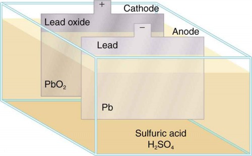
Figure three. Creative person's formulation of a atomic number 82-acrid cell. Chemical reactions in a lead-acid cell separate charge, sending negative charge to the anode, which is connected to the lead plates. The lead oxide plates are continued to the positive or cathode concluding of the cell. Sulfuric acrid conducts the charge too as participating in the chemic reaction.
The details of the chemic reaction are left to the reader to pursue in a chemistry text, but their results at the molecular level assist explicate the potential created by the battery. Effigy 4 shows the consequence of a unmarried chemical reaction. 2 electrons are placed on the anode, making it negative, provided that the cathode supplied two electrons. This leaves the cathode positively charged, because it has lost 2 electrons. In curt, a separation of charge has been driven past a chemical reaction. Annotation that the reaction will non have place unless there is a complete circuit to allow two electrons to exist supplied to the cathode. Nether many circumstances, these electrons come from the anode, flow through a resistance, and return to the cathode. Notation also that since the chemical reactions involve substances with resistance, information technology is not possible to create the emf without an internal resistance.
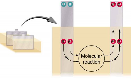
Figure 4. Artist'due south conception of two electrons being forced onto the anode of a cell and two electrons being removed from the cathode of the cell. The chemical reaction in a lead-acid battery places two electrons on the anode and removes two from the cathode. It requires a closed excursion to proceed, since the ii electrons must be supplied to the cathode.
Why are the chemicals able to produce a unique potential departure? Quantum mechanical descriptions of molecules, which accept into account the types of atoms and numbers of electrons in them, are able to predict the energy states they tin accept and the energies of reactions betwixt them.
In the case of a lead-acid battery, an free energy of two eV is given to each electron sent to the anode. Voltage is defined every bit the electrical potential energy divided by charge
[latex]Five=\frac{{P}_{\text{East}}}{q}\\[/latex].
An electron volt is the energy given to a single electron by a voltage of i 5. So the voltage here is ii V, since 2 eV is given to each electron. It is the energy produced in each molecular reaction that produces the voltage. A different reaction produces a different free energy and, hence, a different voltage.
Terminal Voltage
The voltage output of a device is measured across its terminals and, thus, is called its terminal voltage 5. Terminal voltage is given by
V = emf − Ir ,
where r is the internal resistance and I is the current flowing at the time of the measurement. I is positive if current flows away from the positive terminal, equally shown in Effigy 2. You can see that the larger the current, the smaller the final voltage. And it is likewise truthful that the larger the internal resistance, the smaller the terminal voltage. Suppose a load resistance R load is connected to a voltage source, as in Figure 5. Since the resistances are in series, the total resistance in the circuit is R load+r. Thus the current is given by Ohm'due south police force to exist
[latex]I=\frac{\text{emf}}{{R}_{\text{load}}+r}\\[/latex].
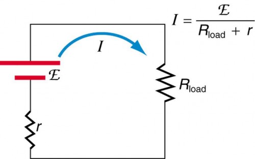
Figure 5. Schematic of a voltage source and its load Rload. Since the internal resistance r is in series with the load, it tin can significantly affect the terminal voltage and current delivered to the load. (Note that the script E stands for emf.)
We meet from this expression that the smaller the internal resistance r, the greater the electric current the voltage source supplies to its load R load. As batteries are depleted, r increases. If r becomes a meaning fraction of the load resistance, then the current is significantly reduced, every bit the following case illustrates.
Example one. Computing Concluding Voltage, Power Dissipation, Electric current, and Resistance: Terminal Voltage and Load
A sure battery has a 12.0-5 emf and an internal resistance of 0.100 Ω. (a) Summate its terminal voltage when continued to a ten.0-Ω load. (b) What is the terminal voltage when connected to a 0.500-Ω load? (c) What power does the 0.500-Ω load dissipate? (d) If the internal resistance grows to0 . 500 Ω, notice the current, terminal voltage, and power dissipated past a 0.500-Ω load.
Strategy
The assay above gave an expression for electric current when internal resistance is taken into account. Once the current is establish, the terminal voltage can exist calculated using the equationFive = emf − Ir. One time current is found, the power dissipated past a resistor tin also exist found.
Solution for (a)
Inbound the given values for the emf, load resistance, and internal resistance into the expression above yields
[latex]I=\frac{\text{emf}}{{R}_{\text{load}}+r}=\frac{12.0\text{ 5}}{{10.1}\text{ }\Omega }=1.188\text{ A}\\[/latex].
Enter the known values into the equationV = emf − Ir to get the concluding voltage:
[latex]\begin{array}{lll}V& =& \text{emf}-{Ir}={12.0\text{ V}}-\left(1.188 \text{ A}\right)\left({0.100\text{ }\Omega}\correct)\\ & =& 11.9 \text{ Five}\stop{array}\\[/latex].
Discussion for (a)
The concluding voltage here is only slightly lower than the emf, implying that x.0 Ω is a calorie-free load for this particular bombardment.
Solution for (b)
Similarly, with R load= 0.500 Ω, the current is
[latex]I=\frac{\text{emf}}{{R}_{\text{load}}+r}=\frac{12.0\text{ V}}{0.600\text{ }\Omega}=xx.0\text{ A}\\[/latex].
The terminal voltage is at present
[latex]\begin{array}{lll}Five& =& \text{emf}-{Ir}= 12.0\text{ Five}-\left(20.0\text{ A}\correct)\left({0.100\text{ }\Omega}\right)\\ & =& 10.0\text{ V}\end{array}\\[/latex]
Give-and-take for (b)
This terminal voltage exhibits a more than significant reduction compared with emf, implying 0.500 Ω is a heavy load for this battery.
Solution for (c)
The power dissipated by the 0.500-Ω load can be found using the formula P=I 2 R. Entering the known values gives
P load=I 2 R load= (20.0 A)2(0.500 Ω) = 2.00 × x2W.
Discussion for (c)
Note that this power can also be obtained using the expressions [latex]\frac{{V}^{2}}{R}\\[/latex] or Four, where V is the terminal voltage (10.0 V in this case).
Solution for (d)
Here the internal resistance has increased, peradventure due to the depletion of the battery, to the signal where it is as great as the load resistance. As before, nosotros first discover the electric current by entering the known values into the expression, yielding
[latex]I=\frac{\text{emf}}{{R}_{\text{load}}+r}=\frac{12.0\text{ 5}}{one.00\text{ }\Omega }=12.0\text{ A}\\[/latex].
Now the terminal voltage is
[latex]\begin{array}{lll}Five& =& \text{emf}-{Ir}=12.0 \text{ Five}-\left(12.0\text{ A}\right)\left({0.500\Omega}\right) & =& half-dozen.00\text{ V}\end{array}\\[/latex].
and the power dissipated by the load is
[latex]{P}_{\text{load}}={I}^{2}{R}_{\text{load}}={\left(12.0\text{ A}\right)}^{two}\left(0.500\text{ }\Omega\correct)=72.0\text{ W}\\[/latex].
Discussion for (d)
We see that the increased internal resistance has significantly decreased concluding voltage, current, and power delivered to a load.
Bombardment testers, such equally those in Figure 6, use small load resistors to intentionally draw current to determine whether the terminal voltage drops beneath an adequate level. They really examination the internal resistance of the battery. If internal resistance is loftier, the battery is weak, as evidenced by its depression terminal voltage.
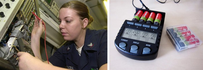
Figure 6. These two battery testers measure terminal voltage under a load to make up one's mind the condition of a battery. The big device is beingness used by a U.S. Navy electronics technician to examination large batteries aboard the aircraft carrier USS Nimitz and has a small resistance that tin can dissipate large amounts of ability. (credit: U.Southward. Navy photo by Photographer's Mate Airman Jason A. Johnston) The small device is used on small-scale batteries and has a digital display to signal the acceptability of their terminal voltage. (credit: Keith Williamson)
Some batteries tin be recharged by passing a electric current through them in the management opposite to the current they supply to a resistance. This is done routinely in cars and batteries for small-scale electrical appliances and electronic devices, and is represented pictorially in Figure 7. The voltage output of the bombardment charger must exist greater than the emf of the battery to contrary current through information technology. This will cause the terminal voltage of the battery to exist greater than the emf, since V = emf − Ir, and I is now negative.
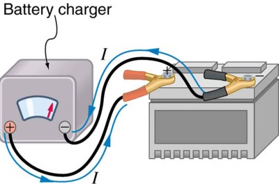
Effigy vii. A car battery charger reverses the normal direction of electric current through a bombardment, reversing its chemic reaction and replenishing its chemical potential.
Multiple Voltage Sources
There are two voltage sources when a battery charger is used. Voltage sources connected in series are relatively simple. When voltage sources are in series, their internal resistances add and their emfs add algebraically. (Run across Effigy eight.) Series connections of voltage sources are common—for example, in flashlights, toys, and other appliances. Normally, the cells are in series in order to produce a larger total emf. Merely if the cells oppose i another, such as when one is put into an appliance backward, the total emf is less, since it is the algebraic sum of the individual emfs. A battery is a multiple connection of voltaic cells, as shown in Figure 9. The disadvantage of series connections of cells is that their internal resistances add together. One of the authors in one case owned a 1957 MGA that had 2 6-Five batteries in serial, rather than a single 12-V bombardment. This system produced a large internal resistance that caused him many problems in starting the engine.
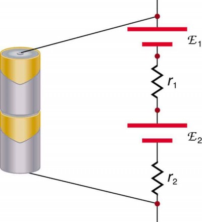
Effigy 8. A series connexion of 2 voltage sources. The emfs (each labeled with a script E) and internal resistances add, giving a total emf of emf1+ emf2 and a total internal resistance of r one+r two.
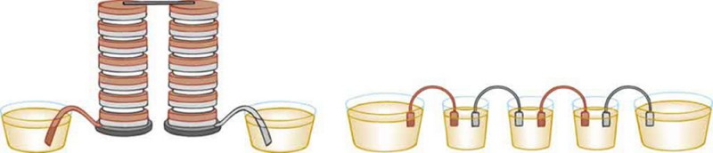
Effigy ix. Batteries are multiple connections of individual cells, every bit shown in this modern rendition of an former impress. Single cells, such equally AA or C cells, are commonly called batteries, although this is technically wrong.
If the series connection of two voltage sources is made into a consummate circuit with the emfs in opposition, so a electric current of magnitude [latex]I=\frac{\left({\text{emf}}_{i}-{\text{emf}}_{2}\right)}{{r}_{ane}+{r}_{ii}}\\[/latex] flows. See Figure 10, for case, which shows a circuit exactly analogous to the battery charger discussed above. If two voltage sources in series with emfs in the aforementioned sense are connected to a load R load, as in Figure eleven, so the following flows:
[latex]I=\frac{\left({\text{emf}}_{1}+{\text{emf}}_{2}\right)}{{r}_{one}+{r}_{2}+{R}_{\text{load}}}\\[/latex]
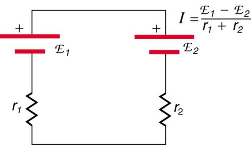
Figure 10. These two voltage sources are connected in serial with their emfs in opposition. Electric current flows in the direction of the greater emf and is limited to [latex]I=\frac{\left({\text{emf}}_{one}-{\text{emf}}_{ii}\right)}{{r}_{1}+{r}_{2}}\\[/latex] by the sum of the internal resistances. (Note that each emf is represented past script E in the effigy.) A battery charger continued to a battery is an example of such a connectedness. The charger must have a larger emf than the battery to contrary current through it.
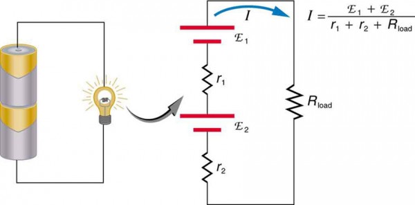
Figure 11. This schematic represents a flashlight with 2 cells (voltage sources) and a single bulb (load resistance) in series. The current that flows is [latex]I=\frac{\left({\text{emf}}_{1}+{\text{emf}}_{two}\correct)}{{r}_{1}+{r}_{2}+{R}_{\text{load}}}\\[/latex]. (Note that each emf is represented by script E in the effigy.)
Have-Home Experiment: Flashlight Batteries
Notice a flashlight that uses several batteries and discover new and old batteries. Based on the discussions in this module, predict the brightness of the flashlight when dissimilar combinations of batteries are used. Do your predictions match what you find? At present identify new batteries in the flashlight and leave the flashlight switched on for several hours. Is the flashlight still quite bright? Do the same with the old batteries. Is the flashlight as bright when left on for the same length of time with old and new batteries? What does this say for the case when you lot are limited in the number of available new batteries?
Figure 12 shows two voltage sources with identical emfs in parallel and connected to a load resistance. In this simple case, the full emf is the same as the individual emfs. Merely the full internal resistance is reduced, since the internal resistances are in parallel. The parallel connection thus can produce a larger current. Here, [latex]I=\frac{\text{emf}}{\left({r}_{\text{tot}}+{R}_{\text{load}}\right)}\\[/latex] flows through the load, and r tot is less than those of the individual batteries. For example, some diesel fuel-powered cars use two 12-V batteries in parallel; they produce a total emf of 12 V merely can deliver the larger electric current needed to start a diesel fuel engine.
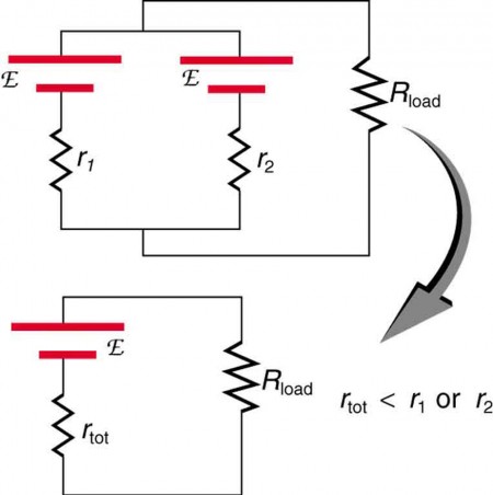
Figure 12. Two voltage sources with identical emfs (each labeled by script E) connected in parallel produce the same emf but have a smaller total internal resistance than the individual sources. Parallel combinations are frequently used to deliver more current. Here [latex]I=\frac{\text{emf}}{\left({r}_{\text{tot}}+{R}_{\text{load}}\right)}\\[/latex] flows through the load.
Animals as Electrical Detectors
A number of animals both produce and detect electrical signals. Fish, sharks, platypuses, and echidnas (spiny anteaters) all detect electric fields generated by nerve activity in prey. Electric eels produce their ain emf through biological cells (electric organs) called electroplaques, which are arranged in both serial and parallel as a set of batteries. Electroplaques are flat, disk-like cells; those of the electric eel have a voltage of 0.15 Five across each 1. These cells are usually located toward the caput or tail of the animal, although in the case of the electrical eel, they are found along the entire body. The electroplaques in the South American eel are bundled in 140 rows, with each row stretching horizontally along the body and containing 5,000 electroplaques. This can yield an emf of approximately 600 V, and a current of 1 A—deadly. The mechanism for detection of external electrical fields is similar to that for producing nervus signals in the cell through depolarization and repolarization—the move of ions across the prison cell membrane. Inside the fish, weak electric fields in the water produce a current in a gel-filled canal that runs from the skin to sensing cells, producing a nerve point. The Australian platypus, one of the very few mammals that lay eggs, can notice fields of [latex]30 \frac{\text{mV}}{\text{yard}}\\[/latex], while sharks have been found to be able to sense a field in their snouts equally small as [latex]100\frac{\text{mV}}{\text{m}}\\[/latex] (Figure 13). Electrical eels employ their ain electric fields produced past the electroplaques to stun their prey or enemies.

Figure 13. Sand tiger sharks (Carcharias taurus), like this ane at the Minnesota Zoo, employ electroreceptors in their snouts to locate prey. (credit: Jim Winstead, Flickr)
Solar Cell Arrays
Some other example dealing with multiple voltage sources is that of combinations of solar cells—wired in both series and parallel combinations to yield a desired voltage and current. Photovoltaic generation (PV), the conversion of sunlight directly into electricity, is based upon the photoelectric result, in which photons hitting the surface of a solar cell create an electric current in the jail cell. Most solar cells are made from pure silicon—either as single-crystal silicon, or as a thin film of silicon deposited upon a glass or metal bankroll. Most unmarried cells have a voltage output of about 0.v V, while the current output is a function of the corporeality of sunlight upon the jail cell (the incident solar radiation—the insolation). Under brilliant noon sunlight, a current of about100 mA/cm 2 of prison cell surface area is produced by typical unmarried-crystal cells. Private solar cells are connected electrically in modules to meet electrical-free energy needs. They can exist wired together in serial or in parallel—connected like the batteries discussed earlier. A solar-prison cell array or module usually consists of between 36 and 72 cells, with a ability output of 50 Due west to 140 W. The output of the solar cells is direct current. For most uses in a home, AC is required, and so a device called an inverter must exist used to convert the DC to Air-conditioning. Whatsoever actress output tin and then be passed on to the outside electrical grid for auction to the utility.
Take-Domicile Experiment: Virtual Solar Cells
I tin assemble a "virtual" solar jail cell array by using playing cards, or business or alphabetize cards, to represent a solar prison cell. Combinations of these cards in series and/or parallel can model the required assortment output. Presume each menu has an output of 0.5 Five and a current (under bright lite) of 2 A. Using your cards, how would you suit them to produce an output of 6 A at 3 V (18 W)? Suppose you were told that you needed only 18 W (but no required voltage). Would you need more than cards to brand this organisation?
Section Summary
- All voltage sources accept 2 fundamental parts—a source of electrical energy that has a characteristic electromotive strength (emf), and an internal resistancer.
- The emf is the potential difference of a source when no current is flowing.
- The numerical value of the emf depends on the source of potential difference.
- The internal resistancer of a voltage source affects the output voltage when a current flows.
- The voltage output of a device is chosen its last voltage V and is given by V = emf − Ir, where I is the electrical current and is positive when flowing abroad from the positive terminal of the voltage source.
- When multiple voltage sources are in series, their internal resistances add and their emfs add algebraically.
- Solar cells can be wired in series or parallel to provide increased voltage or electric current, respectively.
Conceptual Questions
1. Is every emf a potential difference? Is every potential difference an emf? Explain.
2. Explain which bombardment is doing the charging and which is being charged in Effigy xiv.

Figure 14.
3. Given a battery, an array of resistors, and a variety of voltage and current measuring devices, describe how y'all would determine the internal resistance of the battery.
4. Two different 12-V automobile batteries on a store shelf are rated at 600 and 850 "common cold cranking amps." Which has the smallest internal resistance?
5. What are the advantages and disadvantages of connecting batteries in series? In parallel?
6. Semitractor trucks use iv large 12-Five batteries. The starter organization requires 24 V, while normal operation of the truck'south other electrical components utilizes 12 5. How could the 4 batteries be connected to produce 24 V? To produce 12 Five? Why is 24 5 better than 12 V for starting the truck'southward engine (a very heavy load)?
Problems & Exercises
1. Standard automobile batteries take six lead-acrid cells in series, creating a total emf of 12.0 V. What is the emf of an individual lead-acid cell?
2. Carbon-zinc dry cells (sometimes referred to every bit non-alkaline metal cells) have an emf of 1.54 V, and they are produced as single cells or in various combinations to form other voltages. (a) How many 1.54-V cells are needed to make the mutual 9-5 battery used in many small-scale electronic devices? (b) What is the bodily emf of the approximately ix-V bombardment? (c) Discuss how internal resistance in the series connectedness of cells volition affect the terminal voltage of this approximately 9-V battery.
3. What is the output voltage of a iii.0000-5 lithium jail cell in a digital wristwatch that draws 0.300 mA, if the jail cell'due south internal resistance is 2.00 Ω?
4. (a) What is the concluding voltage of a large 1.54-V carbon-zinc dry cell used in a physics lab to supply 2.00 A to a circuit, if the cell's internal resistance is 0.100 Ω? (b) How much electrical ability does the cell produce? (c) What power goes to its load?
5. What is the internal resistance of an automobile battery that has an emf of 12.0 5 and a terminal voltage of 15.0 V while a current of 8.00 A is charging it?
half dozen. (a) Find the terminal voltage of a 12.0-V motorcycle battery having a 0.600-Ω internal resistance, if information technology is being charged by a current of 10.0 A. (b) What is the output voltage of the battery charger?
7. A car battery with a 12-V emf and an internal resistance of 0.050 Ω is being charged with a electric current of 60 A. Note that in this process the battery is existence charged. (a) What is the potential difference beyond its terminals? (b) At what rate is thermal energy beingness prodigal in the battery? (c) At what rate is electric energy being converted to chemic energy? (d) What are the answers to (a) and (b) when the battery is used to supply 60 A to the starter motor?
8. The hot resistance of a flashlight seedling is ii.30 Ω, and it is run by a i.58-5 alkali metal jail cell having a 0.100-Ω internal resistance. (a) What electric current flows? (b) Calculate the ability supplied to the bulb using I 2 R bulb. (c) Is this power the same as calculated using [latex]\frac{{V}^{2}}{{R}_{\text{seedling}}}\\[/latex] ?
ix. The label on a portable radio recommends the employ of rechargeable nickel-cadmium cells (nicads), although they accept a 1.25-5 emf while alkaline cells have a 1.58-Five emf. The radio has a 3.20-Ω resistance. (a) Describe a excursion diagram of the radio and its batteries. Now, calculate the power delivered to the radio. (b) When using Nicad cells each having an internal resistance of 0.0400 Ω. (c) When using alkaline cells each having an internal resistance of 0.200 Ω. (d) Does this divergence seem significant, because that the radio's effective resistance is lowered when its volume is turned upward?
ten. An machine starter motor has an equivalent resistance of 0.0500 Ω and is supplied by a 12.0-V battery with a 0.0100-Ω internal resistance. (a) What is the current to the motor? (b) What voltage is practical to it? (c) What power is supplied to the motor? (d) Repeat these calculations for when the battery connections are corroded and add 0.0900 Ω to the excursion. (Significant bug are caused past even pocket-size amounts of unwanted resistance in depression-voltage, high-current applications.)
11. A child'due south electronic toy is supplied by three one.58-Five alkaline cells having internal resistances of 0.0200 Ω in series with a i.53-V carbon-zinc dry cell having a 0.100-Ω internal resistance. The load resistance is 10.0 Ω. (a) Draw a circuit diagram of the toy and its batteries. (b) What current flows? (c) How much power is supplied to the load? (d) What is the internal resistance of the dry out cell if it goes bad, resulting in simply 0.500 Westward existence supplied to the load?
12. (a) What is the internal resistance of a voltage source if its terminal voltage drops past 2.00 V when the electric current supplied increases by 5.00 A? (b) Can the emf of the voltage source be found with the data supplied?
13. A person with body resistance between his hands of 10.0 kΩ accidentally grasps the terminals of a 20.0-kV power supply. (Do Not do this!) (a) Draw a circuit diagram to represent the situation. (b) If the internal resistance of the ability supply is 2000 Ω, what is the current through his body? (c) What is the power prodigal in his body? (d) If the power supply is to be made safe by increasing its internal resistance, what should the internal resistance be for the maximum current in this situation to be 1.00 mA or less? (e) Will this modification compromise the effectiveness of the power supply for driving low-resistance devices? Explain your reasoning.
fourteen. Electric fish generate electric current with biological cells chosen electroplaques, which are physiological emf devices. The electroplaques in the South American eel are arranged in 140 rows, each row stretching horizontally forth the body and each containing 5000 electroplaques. Each electroplaque has an emf of 0.fifteen Five and internal resistance of 0.25 Ω. If the water surrounding the fish has resistance of 800 Ω, how much current can the eel produce in water from near its head to well-nigh its tail?
15. Integrated ConceptsA 12.0-V emf automobile battery has a terminal voltage of 16.0 5 when being charged by a current of 10.0 A. (a) What is the battery's internal resistance? (b) What ability is dissipated within the battery? (c) At what rate (in ºC/min) volition its temperature increase if its mass is xx.0 kg and it has a specific rut of 0.300kcal/kg ⋅ ºC assuming no heat escapes?
xvi. Unreasonable ResultsA 1.58-V alkali metal cell with a 0.200-Ω internal resistance is supplying 8.50 A to a load. (a) What is its terminal voltage? (b) What is the value of the load resistance? (c) What is unreasonable about these results? (d) Which assumptions are unreasonable or inconsistent?
17. Unreasonable Results(a) What is the internal resistance of a 1.54-Five dry out cell that supplies i.00 W of ability to a 15.0-Ω bulb? (b) What is unreasonable almost this result? (c) Which assumptions are unreasonable or inconsistent?
Glossary
- electromotive strength (emf):
- the potential difference of a source of electricity when no current is flowing; measured in volts
- internal resistance:
- the amount of resistance inside the voltage source
- potential difference:
- the difference in electrical potential betwixt two points in an electric circuit, measured in volts
- terminal voltage:
- the voltage measured across the terminals of a source of potential difference
Selected Solutions to Problems & Exercises
1. two.00 5
3. 2.9994 5
5.0 . 375 Ω
8. (a) 0.658 A (b) 0.997 W (c) 0.997 W; yes
x. (a) 200 A (b) 10.0 Five (c) 2.00 kW (d) 0.1000 Ω;80.0 A, four.0 5, 320 W
12. (a) 0.400 Ω (b) No, in that location is only one independent equation, so only r can be establish.
16. (a) –0.120 V (b) −i.41 × 10−2Ω (c) Negative terminal voltage; negative load resistance. (d) The supposition that such a cell could provide 8.50 A is inconsistent with its internal resistance.
Source: https://courses.lumenlearning.com/physics/chapter/21-2-electromotive-force-terminal-voltage/
 if a 23-v emf is connected to the terminals a and b, what is the current in resistor r1?)
Post a Comment for "(b) if a 23-v emf is connected to the terminals a and b, what is the current in resistor r1?"